

The “WHY” of the Project!.
The increasing number of visually impaired people requires the development of assistive devices around the world. The problem can be solved by using a device that would serve as a smart guide to them. This device for visually impaired people would help them to travel and be self dependent. This is to ensure that impaired humans with disabilities have the tools necessary to fully access and participate in the curriculum, with the greatest possible level of independence. The proposed system can also detect pits in the ground, the obstacle present in the path of visually impaired is informed through vibrator or a buzzer. The device contains ultrasonic sensors at the front and at the sole of the shoe that will detect obstacles and elevations/sink in the ground respectively. The piezo-electric battery charging system will make sure that the device is constantly charged when the subject is on the move as well as used for providing power to various components. A NodeMCU and GPS module will also be installed for easy tracking.
Download from the below mentioned link, the overview of the project.
Technical PPT
- SETTING UP MSP430 LAUNCHPAD :
The MSP430 contains several families, from the low cost Value family to the most advanced F6xx family. Each family is usually targeted at a set of applications and contains a certain mix of peripherals. In a family, however, devices vary as far as the amount of Flash and RAM available. It is not unusual to develop using relatively large devices in a family, only to migrate down to reduce costs. Because of this, the tutorial will end up discussing several platforms, but will attempt to cover the lowest denominator first to make it accessible. The MSP430 Launchpad is the most accessible MSP430 platform and although the devices supported do not have all the peripherals of some of the mode advanced MSP430, it does cover so many peripherals that it makes it an ideal platform for starting.
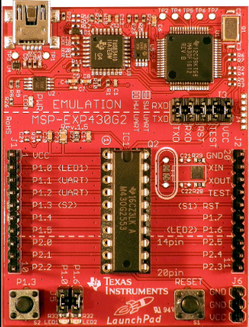
The MSP430 Launchpad is an easy way to get started with the MSP430. For a long time the board was sold at a promotional cost of $4.30, although it’s now available for $9.99. Still, the cost makes it difficult to say no. You can get one from TI’s Website.
The board contains a DIP socket capable of accepting most variants of the MSP430Gxx family. The most common device used is the MSP430G2553(We will be using the same), which is a part running up to 16MHz with 16kB of flash and 512B of RAM. The USB connectivity on the board allows both programming with the on-board JTAG programmer, as well as UART communications for data transfer.
The board can be augmented with booster packs designed by TI and third parties that enable Wireless Communications, Wi-Fi, Batteries, Displays, and other elements. You can find booster packs here.
You can further learn the programming environment for MSP430 i.e ENERGIA IDE
here and come back for the rest of the project,
All about MSP430!
UNDERSTANDING THE SENSORS AND OTHER COMPONENTS :-
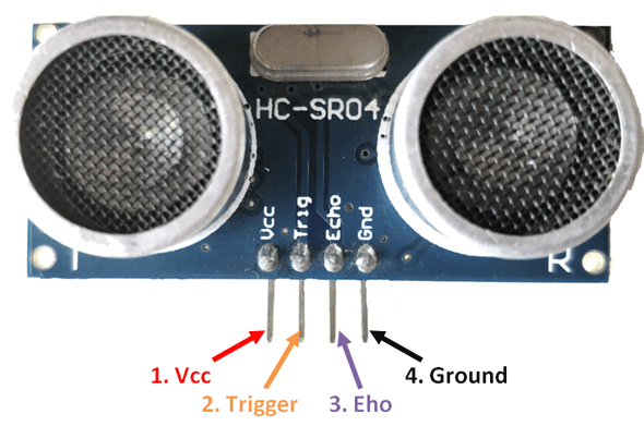
1. Ultrasonic sensors.
Used for detecting obstacles along the path as well as detecting the elevation or sink in the ground. These sensors usually send sound waves for detection of surfaces, liquids, clear objects, and objects in environments. These are based on the measurement of the properties of waves with frequencies above the human audible range often at roughly 40 kHz. They usually operate by generating a high-frequency pulse of sound and then receiving and evaluating the properties of the echo pulse.
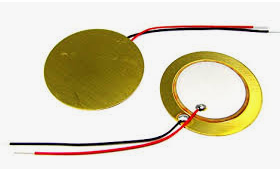
- Piezoelectric transducers.
This circuit will be used for charging the rechargeable battery using the heat generated whilst walking. Although piezoelectric sensors are used for pressure sensing. Piezoelectric sensors may be categorized as either charge mode or voltage mode output. Charge mode sensors are generally used for higher temperature applications above 275° F. They generate a high-impedance charge signal that couples to readout instruments through a low-noise cable and charge amplifier. The charge amplifier serves to convert the sensor’s high- impedance charge output signal to a usable low impedance voltage.
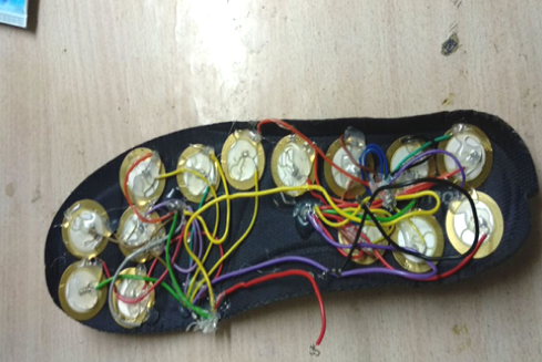
How we set it up in the sole of the shoe :-
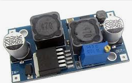
- buck-boost converter.
It is a type of DC to DC converter and it has a magnitude of output voltage. It may be more or less than equal to the input voltage magnitude. The buck boost converter is equal to the fly back circuit and single inductor is used in the place of the transformer. There are two types of converters in the buck boost converter that are buck converter and the other one is boost converter. These converters can produce the range of output voltage than the input voltage. The following diagram shows the basic buck boost converter.
- Interfacing NodeMCU wth GPS module.NEO-6 GPS Module :-
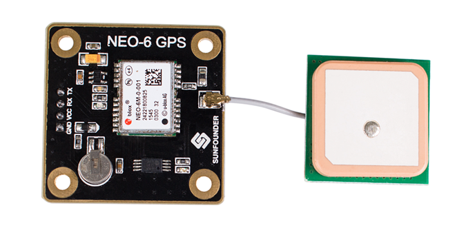
The NEO-6 module series is a family of stand-alone GPS receivers featuring the high performance u-blox 6 positioning engine. These flexible and cost effective receivers offer numerous connectivity options in a miniature 16 x 12.2 x 2.4 mm package. Their compact architecture and power and memory options make NEO-6 modules ideal for battery operated mobile devices with very strict cost and space constraints.The 50-channel u-blox 6 positioning engine boasts a Time-To-First-Fix0(TTFF) of under 1 second. The dedicated acquisition engine, with 2 million correlators, is capable of massive parallel time/frequency space searches,enabling it to find satellites instantly. Innovative design and technology suppresses jamming sources and mitigates multi path effects, giving NEO-6 GPS receivers excellent navigation performance even in the most challenging environments.
NodeMCU:
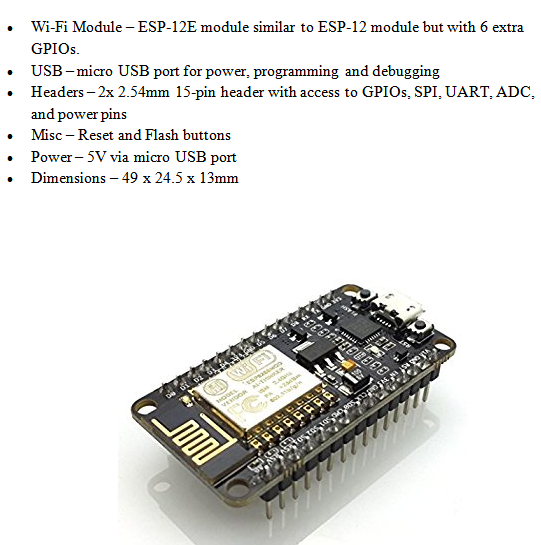
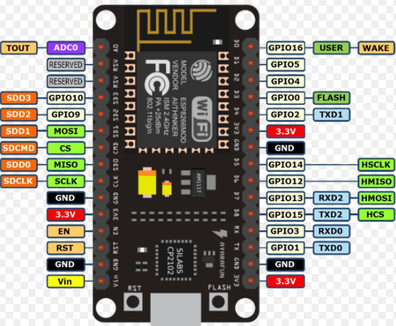
NodeMCU is an open source LUA based firmware developed for ESP8266 wifi chip. By exploring functionality with ESP8266 chip, NodeMCU firmware comes with ESP8266 Development board/kit i.e. NodeMCU Development board. NodeMCU Dev Kit/board consist of ESP8266 wifi enabled chip. The ESP8266 is a low-cost Wi-Fi chip developed by Espressif Systems with TCP/IP protocol. NodeMCU Development board is featured with wifi capability, analog pin, digital pins and serial communication protocols.
To get start with using NodeMCU for IoT applications first we need to know about how to write/download NodeMCU firmware in NodeMCU Development Boards. And before that where this NodeMCU firmware will get as per our requirement.
There is online NodeMCU custom builds available using which we can easily get our custom NodeMCU firmware as per our requirement.
BLYNK APP:
Blynk is a Platform with iOS and Android apps to control Arduino, Raspberry Pi and the likes over the Internet.
It’s a digital dashboard where you can build a graphic interface for your project by simply dragging and dropping widgets.
It’s really simple to set everything up and you’ll start tinkering in less than 5 mins.
Blynk is not tied to some specific board or shield. Instead, it’s supporting hardware of your choice. Whether your Arduino or Raspberry Pi is linked to the Internet over Wi-Fi, Ethernet or this new ESP8266 chip, Blynk will get you online and ready for the Internet Of Your Things.
There are three major components in the platform:
-
- Blynk App– allows to you create amazing interfaces for your projects using various widgets.
-
- Blynk Server– responsible for all the communications between the smartphone and hardware. You can use our Blynk Cloud or run your private Blynk server It’s open-source, could easily handle thousands of devices and can even be launched on a Raspberry Pi.
-
- Blynk Libraries– for all the popular hardware platforms – enable communication with the server and process all the incoming and outgoing commands.
CODE :-
#include <TinyGPS++.h>
#include <SoftwareSerial.h>
#define BLYNK_PRINT Serial
#include <ESP8266WiFi.h>
#include <BlynkSimpleEsp8266.h>
static const int RXPin = 4, TXPin = 5; // GPIO 4=D2(conneect Tx of GPS) and GPIO 5=D1(Connect Rx of GPS
static const uint32_t GPSBaud = 9600; //if Baud rate 9600 didn’t work in your case then use 4800
TinyGPSPlusgps; // The TinyGPS++ object
WidgetMapmyMap(V0); // V0 for virtual pin of Map Widget
SoftwareSerialss(RXPin, TXPin); // The serial connection to the GPS device
BlynkTimer timer;
float spd; //Variable to store the speed
float sats; //Variable to store no. of satellites response
String bearing; //Variable to store orientation or direction of GPS
char auth[] = “93c74fed09574fca8555e792f04ff7ed”; //Your Project authentication key
char ssid[] = “electromaniaweb”; // Name of your network (HotSpot or Router name)
char pass[] = “123456789*/-+”; // Corresponding Password
//unsigned int move_index; // moving index, to be used later
unsigned int move_index = 1; // fixed location for now
void setup()
{
Serial.begin(115200);
Serial.println();
ss.begin(GPSBaud);
Blynk.begin(auth, ssid, pass);
timer.setInterval(5000L, checkGPS);
// every 5s check if GPS is connected, only really needs to be done once
}void checkGPS() {
if (gps.charsProcessed() < 10)
{
Serial.println(F(“No GPS detected: check wiring.”));
Blynk.virtualWrite(V4, “GPS ERROR”);
// Value Display widget on V4 if GPS not detected
}
}void loop()
{
while (ss.available() > 0)
{
// sketch displays information every time a new sentence is correctly encoded.
if (gps.encode(ss.read()))
displayInfo();
}
Blynk.run();
timer.run();
}
void displayInfo()
{
if (gps.location.isValid() )
{
float latitude = (gps.location.lat()); //Storing the Lat. and Lon.
float longitude = (gps.location.lng());
Serial.print(“LAT: “);
Serial.println(latitude, 6); // float to x decimal places
Serial.print(“LONG: “);
Serial.println(longitude, 6);
Blynk.virtualWrite(V1, String(latitude, 6));
Blynk.virtualWrite(V2, String(longitude, 6));
myMap.location(move_index, latitude, longitude, “GPS_Location”);
spd = gps.speed.kmph(); //get speed
Blynk.virtualWrite(V3, spd);
sats = gps.satellites.value(); //get number of satellites
Blynk.virtualWrite(V4, sats);
bearing = TinyGPSPlus::cardinal(gps.course.value()); // get the direction
Blynk.virtualWrite(V5, bearing);
}
Serial.println();
}
By now, we have set up the GPS tracking feature of the shoe we are designing.
How to and where to fit them inside the shoe will be clearly described at the end of the blog post.
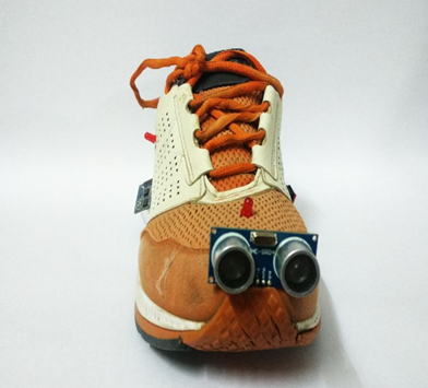
For the time being, we will code the ultrasonic sensors fitted in the front and the sensors fitted downwards at the left and right side of the left and right shoe respectively.
AN OVERVIEW OF THE FUNCTIONALITY OF SENSORS:
FRONT FACING:
The front facing sensors will be coded in such a way so that when an obstacle approaches the user, the vibrators fitted inside the shoe will start vibrating at a minimum frequency thereby giving the user a general idea of the on-coming obstacle, when the obstacle gets closer the frequency of the vibrations will increase proportionately thereby alerting the user to change his course.
DOWNWARD FACING:
They are coded reverse to the front facing sensors. That is, while climbing down the stairs, the shoe of the user will be lifted up and as soon as the shoe is in the air and the user approaches a stair or sink in ground the sensors will vibrate at their maximum threshold and the vibrations will decrease as the user reaches the surface of the stair.
CODE:
#define trigPin1 3
#define echoPin1 4
//#define echoPin2 7
//#define trigPin2 8
#define trigPin3 6
#define echoPin3 5
#define vibrator 10
#define vibrator1 8
long duration, distance, RightSensor,BackSensor,FrontSensor,LeftSensor;
void setup()
{
Serial.begin (9600);
pinMode(trigPin1, OUTPUT);
pinMode(echoPin1, INPUT);
//pinMode(trigPin2, OUTPUT);
//pinMode(echoPin2, INPUT);
pinMode(trigPin3, OUTPUT);
pinMode(echoPin3, INPUT);
pinMode(vibrator,OUTPUT);
pinMode(vibrator1,OUTPUT);
}
void loop() {
SonarSensor(trigPin1, echoPin1);
RightSensor = distance;
/*SonarSensor(trigPin2, echoPin2);
LeftSensor = distance;*/
SonarSensor1(trigPin3, echoPin3);
LeftSensor = distance;
Serial.print(LeftSensor);
Serial.print(” – “);
Serial.print(FrontSensor);
Serial.print(” – “);
Serial.println(RightSensor);
}
void SonarSensor(int trigPin,int echoPin)
{
digitalWrite(trigPin, LOW);
delayMicroseconds(2);
digitalWrite(trigPin, HIGH);
delayMicroseconds(10);
digitalWrite(trigPin, LOW);
duration = pulseIn(echoPin, HIGH);
distance = duration*0.034/2;
if(distance<3)
analogWrite(vibrator,0);
else if(distance>=3 && distance<5)
analogWrite(vibrator,255);
else if(distance>=5 && distance<7)
analogWrite(vibrator,210);
else if(distance>=7 && distance<9)
analogWrite(vibrator,180);
else if(distance>=9 && distance<11)
analogWrite(vibrator,150);
else if(distance>=11 && distance<13)
analogWrite(vibrator,100);
else if(distance>=13 && distance<15)
analogWrite(vibrator,80);
else if(distance>=15 && distance<17)
analogWrite(vibrator,60);
else if(distance>=17 && distance<19)
analogWrite(vibrator,30);
else
analogWrite(vibrator,0);
}
void SonarSensor1(int trigPin,int echoPin)
{
digitalWrite(trigPin, LOW);
delayMicroseconds(2);
digitalWrite(trigPin, HIGH);
delayMicroseconds(10);
digitalWrite(trigPin, LOW);
duration = pulseIn(echoPin, HIGH);
distance = duration*0.034/2;
if(distance<=3)
analogWrite(vibrator1,0);
else if(distance>3 && distance<5)
analogWrite(vibrator1,70);
else if(distance>=5 && distance<7)
analogWrite(vibrator1,100);
else if(distance>=7 && distance<9)
analogWrite(vibrator1,120);
else if(distance>=9 && distance<11)
analogWrite(vibrator1,150);
else if(distance>=11 && distance<13)
analogWrite(vibrator1,190);
else if(distance>=13 && distance<15)
analogWrite(vibrator1,210);
else if(distance>=15 && distance<17)
analogWrite(vibrator1,220);
else if(distance>=17 && distance<19)
analogWrite(vibrator1,240);
else
analogWrite(vibrator1,255);
}
The product you’ll end up with after the necessary hardware connections :

Hi sir can you send me thecircuit diagram of this? Thank you very much.
LikeLike
The circuit connections are standard as given in the code. Let me know if you face any issues @ ajaycrajan@gmail.com
LikeLike